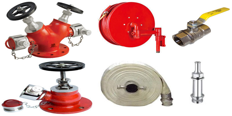
The pump house is arranged to, 1 no. diesel engine driven standby accommodated by, 1 no. electric main pump, 1 no. jockey pump and individual control panel for auto operation of the pumps . Pipeline sizes are selected to get the minimum required pressure at the foremost hydrant point. Internal hydrants arc provided with landing valves and first aid fire hose reels.
For each internal hydrant valves two lengths of 15mtrs long hoses & branch pipes are Provided and kept in fire hose cabinet. Also the first aid hose reel with 30mtrs long rubber hose with shut off nozzle has been provided in internal hydrant system. As regards the operation of the system, it is initiated by the loss of pressure in the pipeline. The system has been charged with pressurized water at 9.0 kg/cm2 .When one more hydrant valves/hose reel are opened, at the time of fire emergency, the pressure drops to actuate the present pressure switch, which in turn actuates the control panel to start the pumps automatically in sequence to discharge sufficient quantity of water.
Internal hydrants form part of any of the following systems :
- Dry-riser system
- Wet-riser system
- Down-comer system
- Wet-riser-cum-down-comer system